

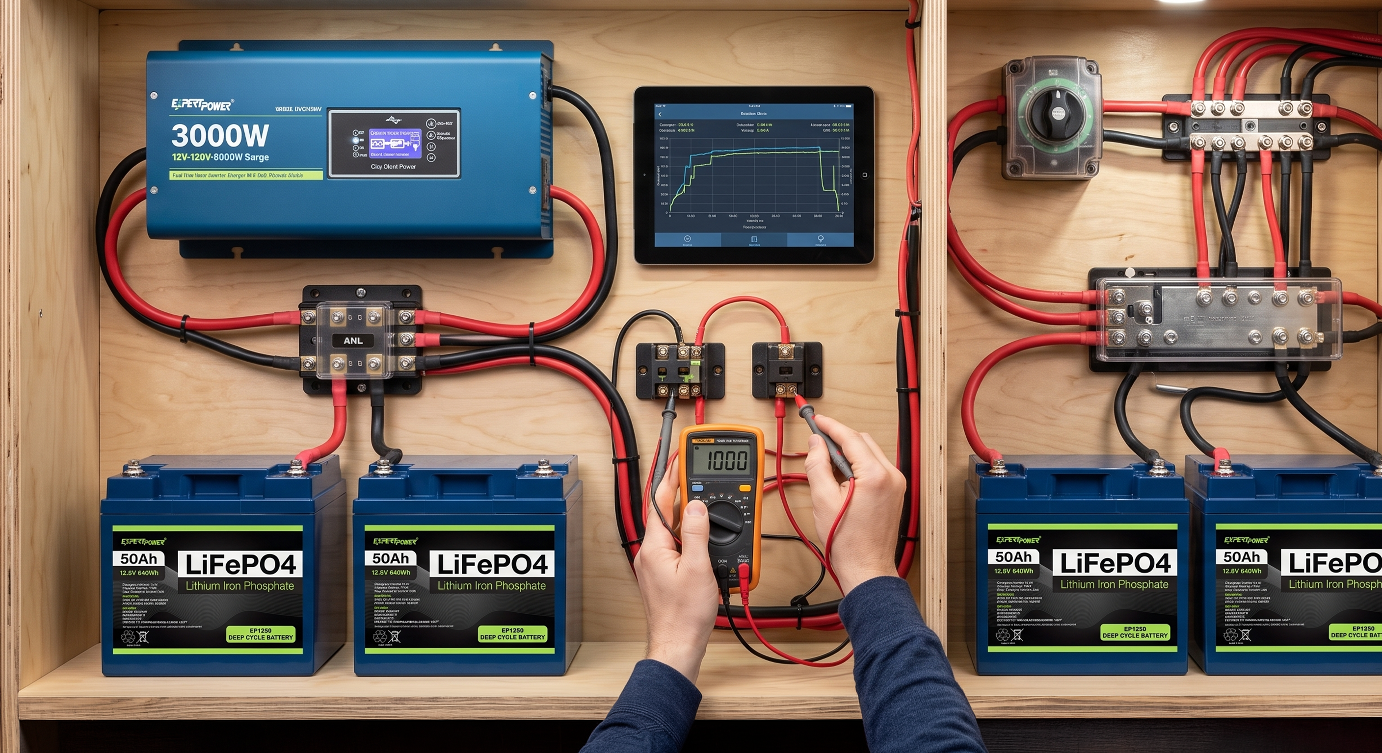


You can invest in top-tier lithium batteries and high-efficiency solar panels, but your entire electrical system is only as strong as its weakest connection. Undersized wiring and improper fusing are the leading causes of mysterious voltage drops, degraded equipment performance, and catastrophic electrical fires in off-grid, RV, and marine power builds. When an electrical setup fails, it rarely starts with the expensive end devices—it starts in the copper connecting it all together.
In this guide, we will demystify American Wire Gauge (AWG), break down voltage drop math without the headache, and clarify exactly when and where to use specific fuses to keep your system safe, efficient, and reliable.
Part 1: The Core Principles of Wire Sizing (Ampacity)
Before running cables across a vehicle or off-grid structure, it is critical to understand how electricity behaves inside a conductor and how physical parameters dictate safety margins.
What is Ampacity?
Ampacity is defined as the maximum continuous current-carrying capacity (in amperes) of a conductor before taking thermal damage or exceeding its insulation temperature rating. Every wire presents natural internal resistance to electrical flow. As current overcomes that resistance, power is converted directly into heat.
The Voltage Factor
A common misconception in power system design is why low-voltage 12V systems require massive, heavy cables compared to higher-voltage setups carrying the exact same power. Power output is governed by the basic formula P = V × I (or W = V × A).
To deliver a continuous 1,200 Watt load across different system voltages:
- At 12V DC: You must transfer 1200W / 12V = 100 Amps
- At 24V DC: You must transfer 1200W / 24V = 50 Amps
- At 48V DC: You must transfer 1200W / 48V = 25 Amps
Because resistive heat generation in a conductor increases with the square of current (Ploss = I2R), lower-voltage systems demand exponentially thicker conductors to move identical power loads safely.
Material Matters: Tinned Copper vs. Alternatives
The chemical composition and physical manufacturing of wiring heavily impact system longevity and performance:
- Marine-Grade Tinned Copper (BC-5W2): Individual fine strands of pure copper are electroplated with tin. This provides exceptional resistance to oxidation and galvanic corrosion while maintaining high flexibility for tight runs.
- Bare Building Copper (e.g., THHN): Typically solid or coarse-stranded copper designed for residential AC applications. It lacks vibration resistance and corrodes rapidly in damp environments.
- Copper-Clad Aluminum (CCA): An aluminum core clad in a thin copper shell. Avoid CCA entirely in DC power systems. CCA possesses roughly 40% higher resistance than pure copper, fractures easily under vibration, and poses elevated thermal risks.
Part 2: Conquering the Voltage Drop Equation
Understanding Resistance Over Distance
Voltage drop represents loss of electrical potential between the power source and the load caused by wire resistance. If a battery bank outputs 13.2V at the terminals, but an inverter receives only 11.8V under load, the 1.4V difference is dissipated along the wiring as waste heat.
The Round-Trip Rule
When calculating circuit length, you must account for the entire current path: the positive wire run from source to load plus the negative return wire back to the source.
Acceptable Thresholds
| Threshold | Application Type | Engineering Justification |
|---|---|---|
| 3% or Less | Critical Loads (Inverters, Battery Chargers, Solar Controllers, Refrigerators) | Prevents premature low-voltage inverter cutoffs and ensures maximum battery charge voltage accuracy. |
| 10% or Less | Non-Critical Loads (LED Lighting, General Fans, Cabin Water Pumps) | Maintains basic functionality where minor efficiency losses do not impact system safety or operation. |
Practical Calculation Example
Suppose we need to size a cable for a 12V DC circuit powering a continuous 50 Amp load across a 10-foot physical distance (20-foot round-trip) with a maximum allowable voltage drop of 3%.
Maximum allowable drop: 12V × 0.03 = 0.36V.
Using the standard DC conductor resistance calculation:
Resistance / 1,000 ft = ( 0.36 / ( 50 × 20 ) ) × 1,000 = 0.36 Ω / 1,000 ft
Evaluating standard American Wire Gauge (AWG) resistance tables:
- 8 AWG: ~0.64 Ω / 1,000 ft → Causes a 5.3% drop (Unacceptable)
- 6 AWG: ~0.40 Ω / 1,000 ft → Causes a 3.3% drop (Borderline)
- 4 AWG: ~0.25 Ω / 1,000 ft → Causes a 2.1% drop (Optimal & Safe)
Part 3: Choosing the Right Fuse Type for the Job
Comparing Primary Fuse Form Factors
1. MRBF (Marine Rated Battery Fuse)
MRBF fuses screw directly onto battery terminals or threaded posts. They offer compact installation and eliminate unprotected cable segments between the battery terminal and external fuse blocks.
2. ANL Fuses
ANL fuses feature a bolt-in blade design suited for medium-to-heavy DC distribution channels, charge controllers, and mid-sized inverters. They provide easy visual inspection and robust physical mounting.
3. Class T Fuses
Class T fuses are fast-acting, high-interrupt ceramic fuses essential for high-capacity Lithium (LiFePO4) battery banks. Lithium chemistries can deliver short-circuit discharge currents exceeding 10,000 Amps.
Standard fuses can suffer from arc-over—where intense current vaporizes the internal element into a conductive plasma bridge, allowing current to flow continuously despite a blown fuse. Class T fuses feature a high Amperage Interrupt Capacity (AIC) of up to 20,000A at 125V DC, extinguishing high-energy arcs safely.
Part 4: Golden Rules of Fuse Placement
1. The "Within 7 Inches" Rule
Position primary circuit fuses as close to the positive power source as physically possible—ideally within 7 inches of the terminal connection (per ABYC standards). Any length of unfused wire between the terminal and fuse holder represents an unmonitored dead-short risk.
2. Upstream Protection
Always place main fuses upstream of switches, disconnects, and distribution blocks. Every junction point, mechanical contact, or terminal lug introduces potential mechanical failure points that require upstream short-circuit protection.
3. Matching Fuse Rating to Conductor Ampacity
Select a fuse rating that is lower than or equal to the continuous ampacity rating of the protected cable, but higher than the continuous operating current of the connected load.
Example: A circuit operating a 40A continuous load wired with 8 AWG marine wire (rated for ~80A continuous):
- Incorrect: 100A Fuse (Wire insulation melts prior to fuse trip during overload).
- Correct: 50A or 60A Fuse (Protects cable while preventing nuisance trips).
Summary Checklist
- Determine Continuous Load: Calculate total sustained amperage draw for the circuit.
- Calculate Round-Trip Distance: Measure out-and-back conductor distance in feet.
- Select AWG for Voltage Drop: Verify voltage drop remains ≤ 3% for critical feeds or ≤ 10% for non-critical loads.
- Mount Fuse Near Source: Install main fuses within 7 inches of battery positive terminals or main busbars.
- Verify Interrupt Capacity: Ensure lithium battery main feeds use high-AIC Class T fuses.
- Align Fuse to Wire Rating: Confirm fuse rating does not exceed wire ampacity limits.
Inspect Your Build Today
Taking time to audit wire gauges, resistance drop calculations, and fuse interrupt ratings prevents costly hardware failures and hazards. Have questions about sizing your next inverter feed or solar array? Review your layout carefully and verify all wire runs prior to commissioning.