

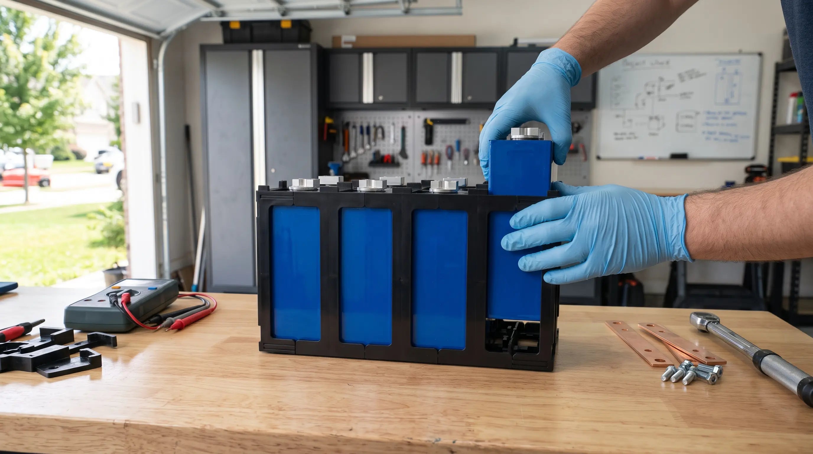


Building a high-capacity energy storage system using raw 3.2V 304Ah LiFePO4 Prismatic Cells offers unmatched cost-per-watt-hour value for RV conversions, off-grid cabins, and marine vessels. However, assembling raw cells into a reliable 12V (4S), 24V (8S), or 48V (16S) bank requires more than just connecting busbars and wiring a BMS.
One of the most debated topics among DIY battery builders is mechanical fixturing: how to safely brace, space, and compress cells to guarantee they reach their full 4,000+ cycle rating without deforming cases or shearing terminal threads.
1. The Physics of Cell Expansion: Breathing vs. Swelling
During normal charge and discharge cycles, lithium ions physically shuttle back and forth between the cathode and anode. As ions insert into the graphite lattice of the anode during charging (intercalation), the anode physically expands. During discharge, it contracts. This microscopic dynamic breathing causes the large aluminum sidewalls of prismatic cells to flex outward on every cycle.
If cells are completely unconstrained:
- Electrode Delamination: Repeated unconstrained expansion loosens contact between internal active material layers and current collector foils, causing rapid capacity loss and spiking internal resistance (IR).
- Permanent Case Deformation: Over hundreds of cycles, transient expansion becomes permanent deformation, bulging the thin aluminum casing and stressing internal safety vents.
2. The Flaws of Improvising With Threaded Rods and Plywood
To counteract expansion, many DIY builders attempt to create makeshift compression jigs using threaded steel rods, nuts, and pieces of plywood or aluminum bar stock clamped across the cell faces. While well-intentioned, this approach introduces significant engineering risks:
- Uneven Pressure Distribution: Prismatic cell manufacturers specify an optimal initial compression range (typically around 300 kgf / ~3,000 N at 30%–50% SoC). Plywood flexes under tension, creating concentrated high-pressure pressure points across cell corners while leaving center faces under-compressed.
- PET Film Abrasion: Raw cells are wrapped in a paper-thin blue polyethylene terephthalate (PET) heat-shrink layer that insulates the aluminum casing (which is electrically live relative to internal chemistry). Rigid flat boards sliding against vibrating cells in mobile setups can rub through this insulation, leading to dangerous casing-to-casing dead shorts.
- Thermal Trapping: Sandwiching large cell faces directly against solid insulating boards eliminates all passive heat dissipation, creating localized thermal pockets in the interior cells of an 8S or 16S bank.
3. Engineered Modular Brackets: The Structural Standard
Instead of relying on crude clamping rigs, modern DIY builds utilize injection-molded, flame-retardant modular mounting brackets. These purpose-engineered components resolve mechanical, electrical, and thermal constraints in one cohesive assembly:
- Perimeter Ridge Alignment: Modular brackets lock firmly onto the top and bottom structural seams of prismatic cells. This directs mechanical support to the strongest reinforced edges of the cell casing, completely avoiding localized pressure on the delicate center face.
- Fixed Inter-Cell Isolation: Built-in structural dividers physically separate adjacent cells, ensuring zero casing contact and eliminating any risk of PET sleeve puncture or shorting under continuous vehicle vibration.
- Thermal Relief Gaps: Engineered spacing between cells permits natural convection airflow, preventing thermal runaway and ensuring uniform temperature distribution across all cells in an array.
4. Protecting Terminal Posts and Busbars Under Vibration
In mobile applications—such as overlanding campers, converted camper vans, and marine power systems—road chatter and wave impacts place intense lateral forces on unanchored cells.
When cells shift relative to one another, that movement transfers straight into the solid copper busbars bolted across the top terminals. This creates mechanical shear stress that can strip female M6/M8 terminal threads, crack laser-welded terminal post bases, and loosen terminal fasteners. A loose busbar connection creates high contact resistance, generating intense localized heat that can melt terminal blocks.
Modular cell brackets mechanically lock the entire pack into a monolithic, rigid block. Because the cells cannot twist or slide independently, busbars experience zero mechanical strain, maintaining factory-spec torque and low-resistance conductivity over thousands of road miles.
Step-by-Step Fixturing Checklist for a 4S/8S/16S Build
- Inspect & Insulate: Verify that each cell's blue PET wrapping is pristine. Place non-conductive epoxy glass (FR4 / G10) sheets between cell bodies for secondary puncture protection.
- Seat Lower Brackets: Lay out your bottom modular brackets on an even work surface and seat each cell squarely into its keyed slot, alternating terminal polarity (+ and -) according to your series circuit diagram.
- Interlock Middle and Top Brackets: Snap corresponding middle brackets and upper locking caps over the top shoulder edges, pressing down until the array locks into a rigid, non-shifting grid.
- Apply Measured End-Plate Tension: If pairing brackets with rigid metal end-plates, tighten tie-rods evenly in an alternating diagonal pattern using a torque wrench. Target moderate structural retention rather than excessive crushing force.
- Torque Busbars to Spec: Bolt down clean copper busbars using a calibrated torque wrench (typically 4–6 Nm for standard M6 studs; never exceed terminal manufacturer ratings).
Build a Professional, Road-Ready Battery Bank
Protect your cell terminals, eliminate short-circuit risks, and maximize cycle longevity with precision-engineered mounting brackets designed for 3.2V prismatic cells.
Shop Prismatic Cells & Mounting Accessories